Relative Sensor Poses
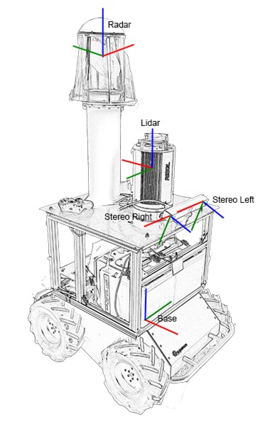
Important reference frames used in the dataset, where x, y, and z axes are represented in red, green, and blue respectively.
Prior to dataset collection, the relative pose between each sensor reference frames was determined. The base frame is centered between the four wheels of the Husky A200, with the x-axis aligned with the forward direction. The pose of the lidar frame is fixed by mechanical design. The translation between the lidar and radar frame is also determined by mechanical design, while the relative rotation was calculated by aligning scans between the two sensors. For the lidar and stereo camera, distinct tie points were manually selected from multiple sets of scans and images to calculate their relative transformation through least squares optimization.
The following table lists the transformations relevant to the dataset, where a rotation brings a point in frame (b) into frame (a), and a translation is defined from frame (b) to frame (a) with respect to frame (a).
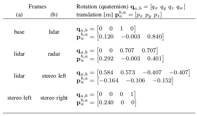
Relative transformation between sensor poses
Camera Parameters
The parameters for the stereo camera were obtained by the standard checker-board calibration process. Specifically, the calibration pipeline implementation in OpenCV was used to obtain the following camera parameters, which assumes the Brown-Conrady distortion model.
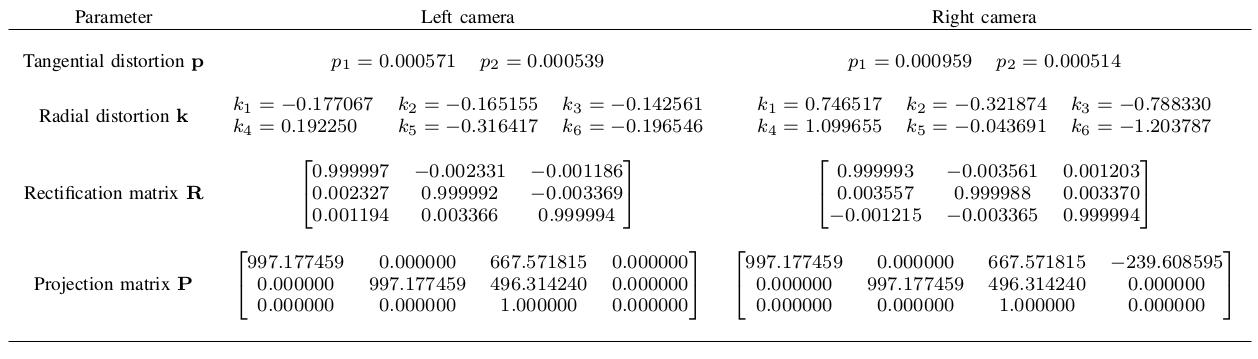
Parameters for the stereo camera
Time Synchronization
A Network Time Protocol (NTP) daemon was used to synchronize the clocks between on-board (data logging and radar server) computers. The computer dedicated to data logging was setup as the NTP server, while the radar server computer was the NTP client. Sufficient time was allowed after booting up both computers for the client clock to adjust. The average time difference is on the order of 0.001 s.