Dataset files are provided in both human readable (ascii text files and png images). For convenience, a binary version is also available in ROS bag format.
Naming Convention
All text files except the groundtruth pose and camera calibration files have file names in the format:
##{S,M}_{encoder,stereo,lidar,radar,timing}.dat
A filename begins with a sequence ID, where ## is a two digit index. S represents data collected while the robot was stationary and the index starts at 00, while M signifies data collected while the robot was moving and the index starts at 01. Hence the dataset was collected in the sequence 00S, 01M, 01S, 02M, … The sequence ID is followed by a string identifying the data type. These are described in greater detail below.
Image files are provided as png files, and their filenames have the format:
##{S,M}_stereo_XXXXXX{L,R}.png
The sequence identifier is the same as the text files. XXXXXX is a six digit integer of the image sequence, and L, R represent left and right camera, respectively.
File Header
Data files have one-line headers that briefly describe the data in each column.
Wheel Encoder Data
Wheel encoder data files are only available for moving sequences. Every line in these (##M_encoder.dat) files follow the format:
[time] [enc_left] [enc_right]
where [time] is the timestamp in seconds, [enc_left] is the calculated distance traveled in meters by the left wheel, and [enc_right] is the calculated distance traveled in meters by the right wheel.
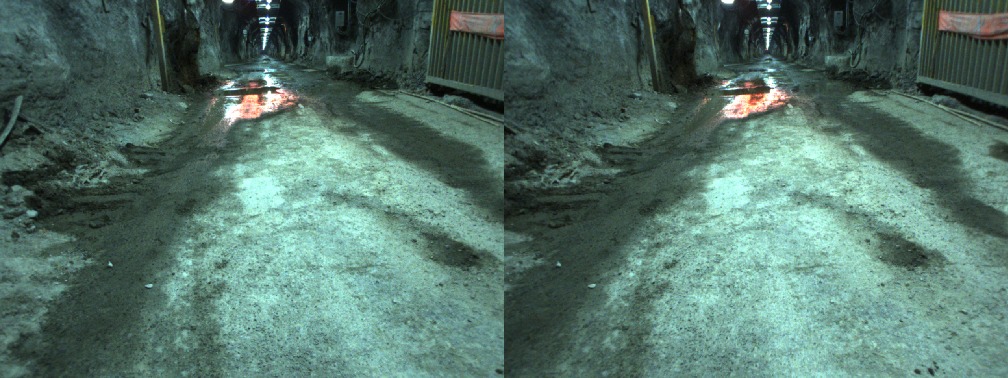
Stereo Images
Text files ##{S,M}_stereo.dat contain timing information for each pair of stereo images. Each line in these files are in the format:
[time] [img_seq]
where [time] is the timestamp in seconds, and [img_seq] is the six digit image sequence index that corresponds with the index used for the png image files.
3D Lidar Point Clouds
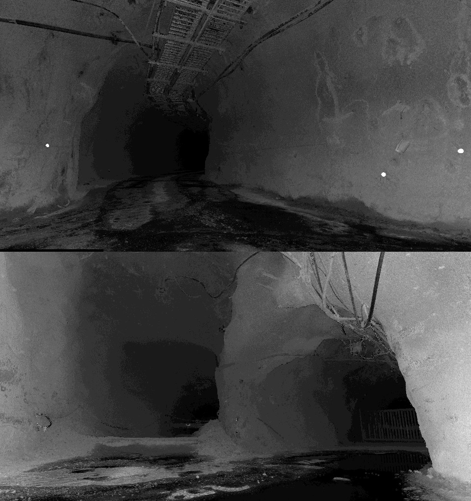 Each line in ##{S,M}_lidar.dat files represent a point in the format:
[time] [x] [y] [z] [i]
where [time] is the timestamp in seconds, [x] [y] [z] are coordinates of a point in meters expressed the lidar frame, and [i] is the intensity of a point.
Radar Data
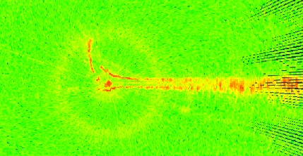 Each line in a radar data file ##{S,M}_radar.dat corresponds to a scan sector defined by the angle of the radar swashplate, and the range bin. The format is:
[time] [x] [y] [p]
where [time] is the timestamp in seconds, [x] [y] are the coordinates of the scan sector’s centre in meters, and [p] is the received power in dB
Timing File
To facilitate the reading of sensor data of interest from the various files in the proper order, timing information from all sensors are summarized in ##{S,M}_timing.dat files. Each line of the file is in the format:
[time] [S]
[time] is the timestamp in seconds, and [S] is a single character from {W, C, L, R} representing wheel encoder, stereo camera, lidar, and radar respectively.
Sensor Relative Poses
The relative transformation between sensors are recorded in a frames.dat file. A transformation that brings a point to frame a from frame b using a rotation quaternion [q_x q_y q_z q_w] and translation vector [p_x p_y p_z] in meters is written in two lines in the format:
[frame_a] [frame_b]
[q_x] [q_y] [q_z] [q_w] [p_x] [p_y] [p_z]
Camera Calibration Data
Camera calibration parameters are stored in a camera.dat file. The file contains eight lines, with the first four lines containing rectification information for the left stereo camera, and the last four for the right stereo camera. Each set of four lines lists, in order, the tangential distortion parameters, radial distortion parameters, the rectification matrix, and the projection matrix (both in row-major order). The following are the lines corresponding to the left camera:
[p_l] [p_1] [p_2]
[k_l] [r_1] [r_2] ... [r_6]
[R_l] [R_1,1] [R_1,2] ... [R_3,3]
[P_l] [P_1,1] [P_1,2] ... [P_4,4]
Scan Pose Estimates
Estimates for the 44 stationary scan positions are recorded in the file scanPoseEsimates.dat. Each line begins with the data sequence identification (e.g., 00S for the first stationary data collection pose), followed by the orientation (expressed as a rotation quaternion) and the scan position in meters, relative to the first stationary data collection pose:
[seq_id] [q_x] [q_y] [q_z] [q_w] [p_x] [p_y] [p_z]